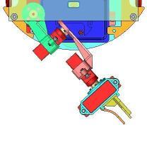
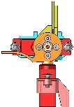
Design of the robot : the Robotic Arm
-
Description :
The connection with the base is carried out by the fixing of the first servomotor with the help of two M3 screws.
.
-
Modeling :
|
Design of the arm
Draft of the robotic arm (Pdf, 246 Ko)
|
-
Calculation of mass properties :
Propr_masse_bras_prehenseur.xls
Note : a calculation page permits to recapitulate each part influence and to adjust if necessary properties of the elements.
-
Mass properties with TopSolid'Design :
Note : select the context Attributes
 , the fonction Material
  and choose : Manager materials. Then create a specific material (Mat_comp_Servo) in the category Miscellaneous, with density 1.72 kg/dm3.
2°) we open the ROBOT ASSEMBLY file and we apply the fonction Analyse element
 with physical informations display to the Arm Tiny-S compact D.
-
Servomotors rotations :
The design of the arm includes angular drivers to parameter its position. We just have to select the tool Modify élément  , click on the arm to accede to the menu list of the four angular position parameters.

Rotation angle arm (servo 1) :
| C = -28° | C = +42° |
 |
 |
Lowering angle arm (servo 2) :
| B = +45° | B = -90° |
 |
 |
Rotation angle wrist (servo 3) :
| A = -90° | A = +90° |
 |
 |
Gripper opening angle (servo 4) :
| Angle +90° | Angle -10° |
 |
 |

